
Quick and dirty 5 minutes craft: Draw a rough shape, define the contact surfaces & load, click run, and get the optimized shape. The last step is converting the output to a printable shape and running one more simulation to double-check it is strong enough.
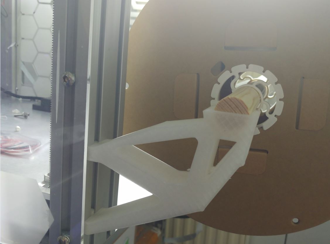
This particular holder is a filament spool holder designed to be loaded with up to 5.5kg of filament (1x2.5kg, 3x1kg).
Nastran.
Is there any software that does take toolpaths into account?
Not as far as I know. The next best option is to define anisotropic properties in the z-direction but this doesn’t close the gap between simulation and slicer output.
How good is it? Good enough. Work with safety margins and temper the print if it is close. An important aspect to make Ansys, Nastram, … work with FDM is experience/rule of thumb. Knowing how to read the result and how to set up a simulation/model to get close enough results.
Most valuable is where and how it will fail as this is pretty accurate. For the exact load capacity it is the simulation result decreased by some rule of thumb based on experience.
Very cool!
Evidently nastran is headless. Did you use a GUI wrapper/interface? If yes, which one?
Final question: is this object the typical x wall thickness and y infill part? Did you happen to check the weight of a solid and optimized part? There’s no doubt in my mind that this would save mass if it was a solid part, but if it’s fairly hollow I wonder if the extra walls actually resulted in a heavier part.
Inventor has a GUI for it. There are more options.
A slightly higher wall count for prints and the weight of the unoptimized solid is pointless in this instance as it starts with a larger slab and tell it to remove x% of weight. With the simulation result you either increase or decrease the x% removed setting and run it again till the load part strength is correct. Very basic in this regard but this was a quick design. How the spool is relative to the mounting points isn’t optimized. It was just me drawing something.
This particular part is 70g each with the filament being approx. 100mm moved forward (leaver length) and were simulated to withstand roughly 12kg and tested with 5.5kg+spool weights.